NOTE: Confluence Cloud migration has completed - switch there. Do not modify anything here! / PanuO
Technical features
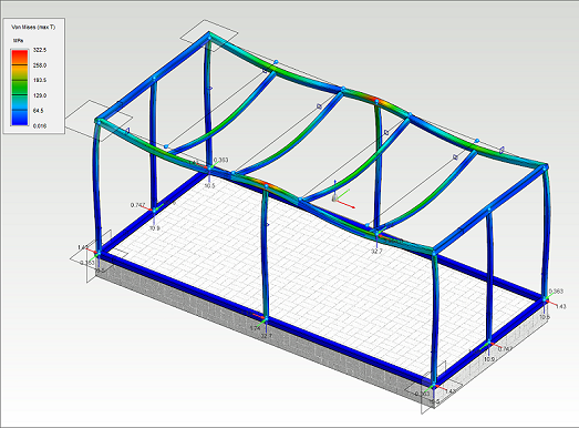
FEA for Beams and Frames supports linear static analysis for profile structures. Profile members of the analysis can be modeled in Vertex or be extruded from standard cross sections. Displacements and stresses can be solved by FEA analysis.
Type of finite element
FEM element type of the analysis is based on Euler-Bernoull beam theory, where nodes contains six degrees of freedom. The analysis supports straight beam elements with standard cross sections. The beam element can be stressed by compress, bending and torsional stresses.
The beam model is improved by taking care of shearing deformation caused by shear stress. Shear strains are considered by the shear areas.
Material model
FEA uses linear and elastic material model.
Cross sections
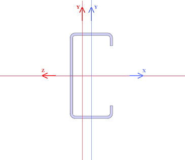
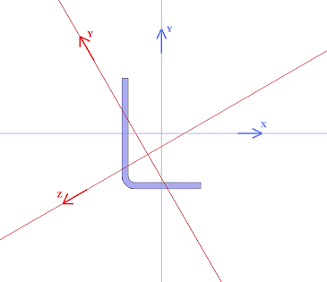
The local coordinate system of the cross section in Beams and Frames FEA is shown in the cross section figure. The local coordinate system of the cross section
- origin point locates in the neutral axis of the cross section
- X axis is aligned with the direction of the beam
- Y axis is the first main direction of the cross section
- Z axis is the second main direction of the cross section
- The first main direction is always the more strength direction against the bending, condition lz > ly is true always
Note!
The modeling coordinate system of the cross section is different than the local coordinate system, which is used in FEA. The local coordinate system in FEA is the same as the main principal coordinate system of cross section.
- In the figures below
- Blue one is the modeling coordinate system
- Red one is the local coordinate system
Cross section values of the beam and truss FEA members are defined automatically by 3d model. Next cross section values are defined for all members:
- Cross section area
- Moment of inertia in the first main direction
- Moment of inertia in the second main direction
- Section modulus in the first main direction
- Section modulus in the second main direction
Additionally, if the shape of the cross section is recognizable, next values are defined:
- Torsion modulus
- Section modulus in torsion
- Shear area in the first main direction
- Shear area in the second main direction
The shear center is assumed to be located at the centroid of section.
Shear area is defined as cross sectional area considering the influence of shear forces. Shear area is sometimes presented as a shear coefficient by the equation

,where
- κ = shear coefficient
- As = shear area
- A = cross section area
Recognizable beam and truss structure cross sections are:
- I-profile
- L-profile
- U-profile
- C-profile
- Z-profile
- T-profile
- Round
- Ellipse
- Round tube
- Rectangle
- Hollow rectangle
If the cross section shape is not recognizable, shear area, torsion modulus and section modulus in torsion values are zero.
If shear area values are zero, shear strain is excluded in the analysis.
All cross section values can be overwritten by user.
Node supports and connections
Beam and truss element nodes can be supported or be linked to the main nodes by defining degrees of freedom.
Degree of freedom of node can have three different states:
- Free
- Supported
- Linked
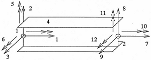
Loads
Next load types can be applied for beam and truss structures:
- Point load
- Point moment
- Line load
- Forced displacement
- Heat load
- Area load
The result of the analysis
Next stress types are solved in the analysis of beam and truss structures:
- Normal force
- Shear forces along the main direction of the cross section
- Bending moments along the main direction of the cross section
- Torsional moment
- Normal stress along the beam axis
- Von Mises stress
- Support reactions
- Displacement
User interface
The user interface of FEA contains graphics of 3d model, study tree and ribbon menu commands. All commands are pointed into the active study. Passive studies are shown grey in the study tree.
Open the FEA state as follows:
- Check that nothing is selected in the work window by pressing Esc.
- Select from contextual menu FEA >
 FEA for Beams and Frames or FEA >
  FEA for Solids and Assemblies
Return to the normal modeling mode as follows:
- Select
 OK. All changes for the active study are saved.
 - Select
 Exit. All changes for the active study are discarded.
Modifications of 3d model is restricted in the FEA state.