NOTE: Confluence Cloud migration has completed - switch there. Do not modify anything here! / PanuO
This example shows how to build a FEM analysis model for a CFS truss and how to examine the displacements and stresses. Top chords of the truss are loaded by a 4 kN/m linear load.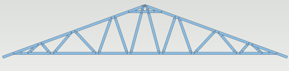
Self-weight of study members are included into this study. All connections are considered as a joints.
Create a new study
- Open FEA for Beams and frames functionality from contextual menu FEA >
 FEA for Beams and Frames
 - Create a new study by selecting wall panel members and pressing
 New study from ribbon tab.
 - Fill study information. Set Self-weight of profiles selected.
- As default, each member of the study consist of one FEM beam element, when both ends of the member contains a node. All members are connected with a joint connection and they can rotate freely about Y axis.


Link nodes
- Select all parts of the study by pressing Select parts from the contextual menu of the active study in study tree.
- Link the nodes of selected parts by pressing
 Link from the contextual tab. Set automatic tolerance on and
  Hinged about transverse axis Y as connection between nodes.
 - Press OK. All study members are now connected with joint connections.

Set supports
- Select the end node of bottom chord. Change its status to main node by pressing Main node checkbox from the contextual tab.

- Set the selected node supported by pressing Hinged >
 About axis Y from contextual tab.
- Repeat steps 1 and 2 for the other end node of the bottom chord.
- Change one of the supported nodes to sliding hinge by freeing its translational degree of freedom in X direction.

Set loads
- Start adding a linear load to the top chord of the truss by selecting
 Linear load from the ribbon tab. The linear load is set between two user defined nodes.
 - The FEM analysis model is now ready for solving.

Solve the study
- Select
 Solve from ribbon tab.
 - Change stress plot to Displacement. Set Show force reactions on.

- Change stress plot to Von Mises stress.

- Press Quit. Select the top chord of the truss and press Hide Others from the contextual menu.
- Solve the study. Change stress plot to Bending moment MY and set results display to Diagram. Set Hide profiles on. Now the bending moment diagram only for the top chord is shown.
