NOTE: Confluence Cloud migration has completed - switch there. Do not modify anything here! / PanuO
Load can be directed to node, node gap or part depending on load type.
Loads of active study can be selected from 3d model or study tree.
- Load is selectable when a small circle appears next to the cursor.
- Selected loads are shown in highlight color in 3d model.
- Hold Ctrl to select multiple loads.
- Load selection can be cleared by clicking empty space from 3d model or pressing Esc.
Visible and selectable loads can be filtered by selecting parts of active study. Only loads belonging to selected parts are visible and selectable.
Create load
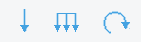
- Select load function from ribbon tab.
- Select node, node gap or part depending on the load type.
- The properties of created loads can be defined in the opened dialog.
- Name can be defined for every load type.
- Other properties for loads are listed in the table below.
| Load | Defined for | Properties | Remarks |
|---|---|---|---|
| Point load | node |
| |
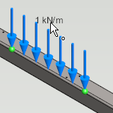
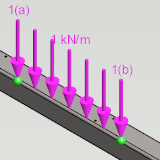
| Linear load | node gap |
| nodes of defined node gap must belong to the same beam |
| Moment | node |
| |
| Forced displacement | node |
| defined node must be supported, otherwise forced displacement will be ignored |
| Temperature load | part |
| Temperature load can be given so that its value is changing in the section main directions. The temperature gradient defines that change. The given temperature load is affecting in the section centroid and the change is positive along the main directions. |
| Area load | parts |
| Area loads are defined between border profiles |
- There are several options to define the direction of load. The direction is defined by the functions of load dialog. When using these functions the load direction is shown real time in 3d model.
- Press Select surface and pick a surface from 3d model. The load direction will be the normal of selected surface.
- Press Select 2 points and pick start and end point for the load direction from 3d model.
- Press Gravity. The load direction will be the gravity direction defined in study information.
- Press X, Y or Z. The load direction will be parallel to selected axis of 3d model global coordinate system.
- Press R. The load direction will be reversed.
Edit load
- Select one or more loads.
- Press Properties from contextual menu.
- Load properties can be edited in the same way as when creating load.
Load can also be edited by double clicking it from 3d model or study tree.
Consider self-weight of profiles
- Select study from study tree.
- Go to edit study information by pressing Edit from contextual menu.
- Set Self-weigth of profiles checked.
- Direction of gravity and gravitational acceleration can also be defined.
- Direction of gravity and gravitational acceleration can also be defined.
- Press OK.
The self-weight of profile is considered when there is a blue half cone in the middle of profile in 3d model.
The self-weight of individual profiles can be ignored by setting their density to zero.
Manage visibility of loads
- Select one or more loads.
- Open contextual menu with right-click.
- Manage the visibility of loads with functions Hide, Restore and Hide other loads.
- Hiding of loads hide them from 3d model. In study tree they are shown in grey color.
- Hiding of loads hide them from 3d model. In study tree they are shown in grey color.